- 您现在的位置:买卖IC网 > Sheet目录251 > SM05-7 (Diodes Inc)TVS DIODE 300W 5V 2CH UNI SOT-23
SM05
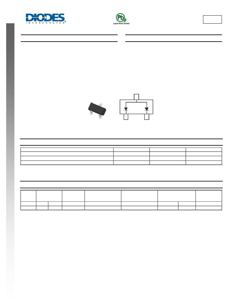
DUAL SURFACE MOUNT TVS
Features
Mechanical Data
?
?
?
?
?
?
?
300 Watts Peak Pulse Power (tp = 8x20 μ s)
IEC 61000-4-2 (ESD): Air – 15kV, Contact – 8kV
Dual Common Anode TVS
SOT-23 Package Allows Either Two Separate Unidirectional
Configurations or a Single Bidirectional Configuration
Lead Free/RoHS Compliant (Note 3)
“Green” Device (Note 4)
Qualified to AEC-Q101 Standards for High Reliability
?
?
?
?
?
?
?
Case: SOT-23
Case Material: Molded Plastic, “Green” Molding Compound,
Note 3. UL Flammability Classification Rating 94V-0
Moisture Sensitivity: Level 1 per J-STD-020
Terminals: Matte Tin Finish annealed over Alloy 42 leadframe
(Lead Free Plating) Solderable per MIL-STD-202, Method 208
Ordering Information: See Page 2
Marking Information: See Page 2
Weight: 0.0089 grams (approximate)
Thermal Characteristics
Top View
Device Schematic
Characteristic
Symbol
Value
Unit
Peak Pulse Power (tp = 8x20 μ s)
Thermal Resistance, Junction to Ambient
Operating and Storage Temperature Range
(Note 6) T A = 25°C
(Note 6) T A = 25°C
P pk
R θ JA
T J , T STG
300
417
-55 to +150
W
° C/W
° C
Electrical Characteristics
@T A = 25°C unless otherwise specified (Note 7)
Reverse
Standoff
Voltage
Breakdown
Voltage
V BR @ I T
Test
Current
Max. Reverse
Leakage @ V RWM
(Note 5)
Max. Clamping
Voltage @ I PP = 5A
(Note 2)
Max. Clamping Voltage
V C @ I PP (Note 2)
Typical
Capacitance C T
(Note 1)
V RWM (V) Min (V) Max (V)
5 6.2 7.3
I T (mA)
1.0
I R ( μ A)
10
V C (V)
9.8
V C (V)
20.6
I PP (A)
17
(pF)
230
Notes:
1.
2.
3.
4.
5.
6.
V R = 0V, f = 1MHz.
Clamping voltage value is based on an 8x20 μ s peak pulse current (I pp ) waveform.
No purposefully added lead.
Diodes Inc.’s “Green” policy can be found on our website at http://www.diodes.com/products/lead_free/index.php.
Short duration pulse test used to minimize self-heating effect.
Device mounted on FR-4 PC board with suggested pad layout, which can be found on our website at http://www.diodes.com/datasheets/ap02001.pdf.
Measured across pin 1 and pin 2.
SM05
Document number: DS31828 Rev. 4 - 2
1 of 4
April 2010
? Diodes Incorporated
发布紧急采购,3分钟左右您将得到回复。
相关PDF资料
SM1000RMNAFTA
UPS 1000VA 640W 6OUT RACK/TOWER
SM1050NAFTA
UPS 1050VA 705W 6OUT TOWER
SM1500NAFTA
UPS 1500VA 980W 6OUT TOWER
SM1500RMNAFTA
UPS 1500VA 1000W 8OUT RACK/TOWER
SM1500XLNAFTA
UPS 1500VA 980W 6OUT TOWER
SM2200NAFTA
UPS 2200VA 1700W 6OUT TOWER
SM2200RMNAFTA
UPS 2200VA 1600W 8OUT RACK/TOWER
SM24T1G
TVS DIODE ARRAY 24V SOT-23
相关代理商/技术参数
SM057A102JAL120
制造商:AVX Corporation 功能描述:- Bulk
SM057A102JAN120
制造商:AVX Corporation 功能描述:- Bulk
SM057A102JBL120
制造商:AVX Corporation 功能描述:- Bulk
SM057A102KAN120
制造商:AVX Corporation 功能描述:- Bulk
SM057A102KBL120
制造商:AVX Corporation 功能描述:NPO,.001UF,10%,500V,BLK,SN/PB - Bulk
SM057A103JAL120
制造商:AVX Corporation 功能描述:- Bulk
SM057A103JAN120
制造商:AVX Corporation 功能描述:- Bulk
SM057A103JBN120
制造商:AVX Corporation 功能描述:- Bulk
